Soldering II

Soldering on Temperature-Sensitive Substrates

Published – 11/14/2022
AuthorAra Parsekian, Ph.D
Download as a PDF 

Published – 11/14/2022
AuthorAra Parsekian, Ph.D

Designers are constantly looking for new ways to add functionality to their latest and greatest products. Previously, in our Soldering I article, we discussed the synergy between form and function made possible by constructing circuits on temperature-sensitive substrates. In this article, we will focus on the photonic soldering of temperature-sensitive components. Similar to how PET flex melts before most solder alloys reflow, some components are incapable of surviving the journey through a reflow oven. That complicates the assembly process for PCBs incorporating those components and sometimes forces costly design workarounds.
To get around thermal constraints, PulseForge soldering brings two big advantages to the table: non-equilibrium heating and spatial selectivity. Both advantages mean that solder can reflow while critical parts of the board remain undamaged. They allow high-temperature solder and low-temperature materials to coexist on the same PCB. And they empower developers to design a product, with fewer constraints from the process required to arrive at that product.
To demonstrate these advantages, let’s first consider batteries. Across wearables, mobile devices, IoT, and many more conventional applications, batteries are a necessity when something has to function without a direct electrical connection to the grid. However, enduring a full reflow cycle in a convection oven degrades the performance and reliability of most batteries. For this reason, batteries are typically assembled on the board after the reflow oven, and rarely soldered directly to the PCB. Yet in the test vehicle pictured here, direct solder attachment of batteries is simple and easy with the PulseForge platform.
Soldered battery test vehicle

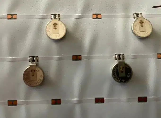
FIGURE 1: soldered battery test vehicle

PulseForge is a high-power, low-energy process, where the subtle distinction between heat and temperature has spectacular consequences. In this case, the battery has more thermal mass than the pads and solder paste around it. Thus, considerably more heat is required to raise the battery temperature than to reflow the solder, even though both solder and battery receive a similar dose of radiant energy. This is the key principle that makes it possible for PulseForge soldering to attach a tabbed battery together with the other SMT components on the board.
Simulation of soldered battery

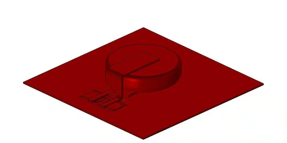
FIGURE 2: simulation of soldered battery

As a second example, let’s consider flex connectors and wires. Although these can (and often do) incorporate high-temperature oven-proof insulation, they still experience expansion and warping that makes attachment tricky. In practice, cable-to-cable and cable-to-board connections almost always rely on mechanical crimps and headers. This works just fine in most cases, but it can be constraining when space and weight are at an absolute premium. By contrast, direct solder connections between flex cables and boards represent the absolute best-case scenario for cramming functionality into a specific size and shape.
Soldering temperature sensitive components - Header for flex connector

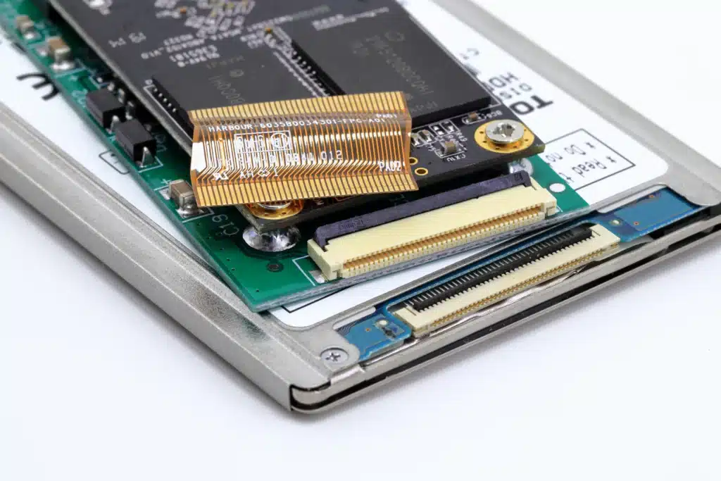
FIGURE 3: header for flex connector

This is where the selectivity advantages of PulseForge soldering really come in handy. Because energy transfer in photonic soldering is based on light, specific parts of the board can be shielded from heating using an opaque barrier – i.e. a photomask. It is also possible to fixture cables against thermal bending and warping during the photonic soldering process, provided the fixture is constructed from a transparent material that does not block light. With this combination of light shielding and transparent fixturing, PulseForge soldering provides a uniquely effective pathway to direct attachment of flex cables. Even low-temperature cables can be soldered using this strategy!
Soldering on temperature sensitive components - Direct cable connection

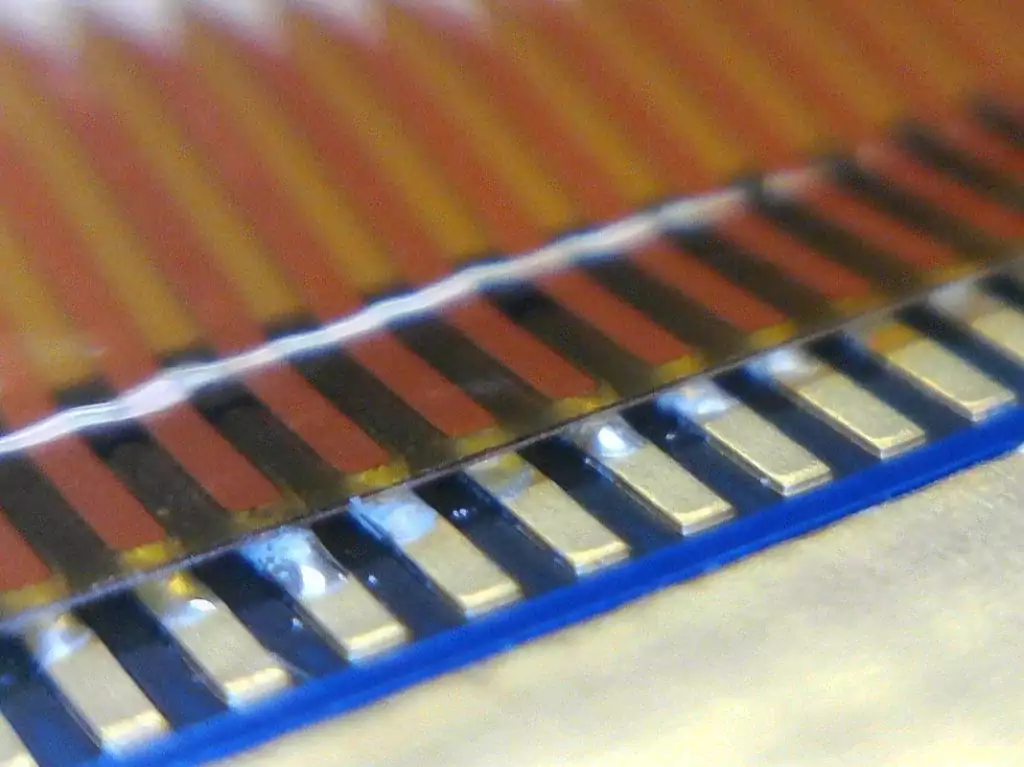
FIGURE 4: direct cable connection

In addition to these examples, the specifics of many a design project involve temperature limits that constrain how a PCB can be built. Of course, there are certainly workarounds that designers can use to get around the reflow step, or do away with solder altogether. But workarounds are taken out of necessity, and typically with some reluctance – they can increase unit costs, complicate supply chains, and sometimes, they can be the difference between a proof-of-concept and a viable commercial product. Photonic processing can be a powerful means to do away with the process workarounds and design the best product possible using materials that are not usable with legacy thermal processes.

*Please download PDF for references and citations.

Ara Parsekian

Ara Parsekian, Ph.D.
Applications Engineer,
PulseForge Inc

Related PulseForge in Research
Ara Parsekian

Ara Parsekian, Ph.D.
Applications Engineer,
PulseForge Inc

Related PulseForge in Research