Digital Thermal Processing™ Frequently Asked Questions

We try to answer some of the most common issues/questions encountered with Digital Thermal Processing.

General Questions

Questions about flash lamps, general machine operation, and specific information of PulseForge Digital Thermal Processing tools.

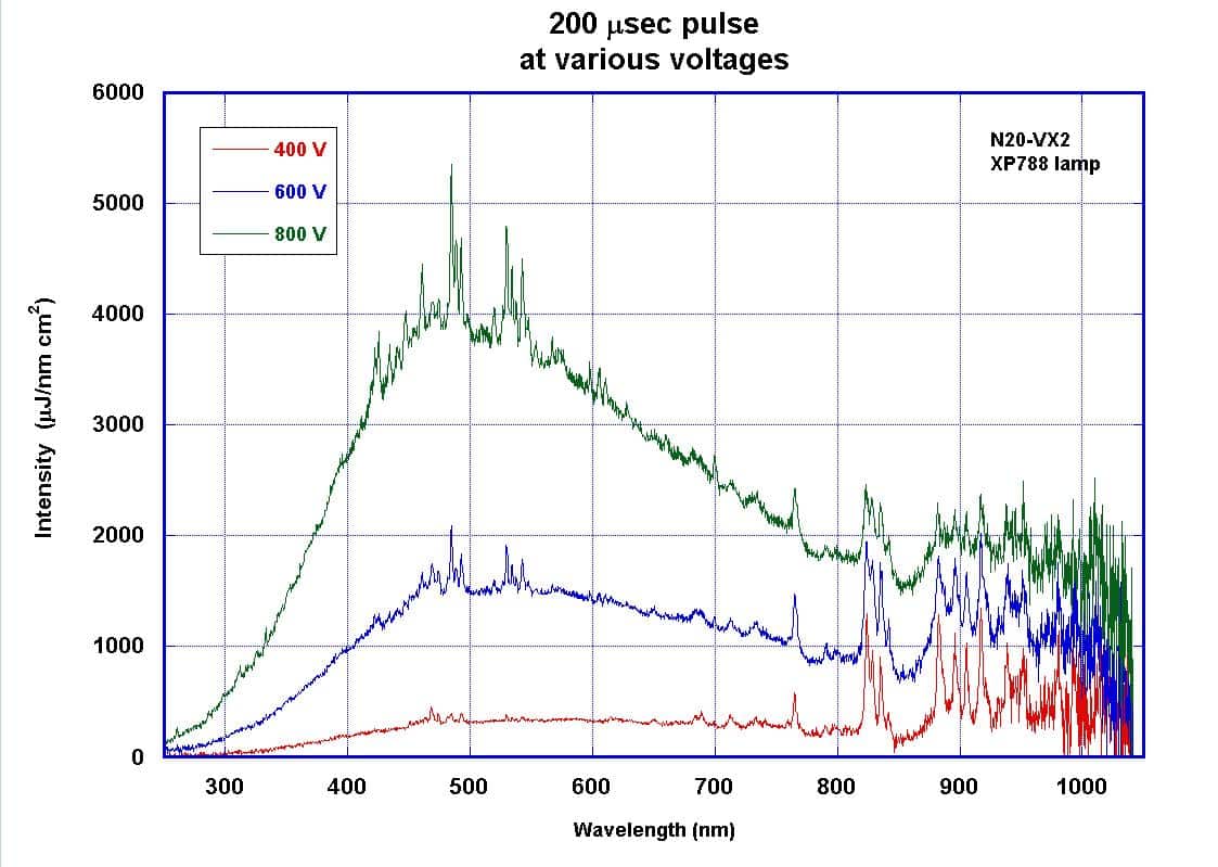
The emission from the PulseForge is broadband ranging from approximately 200nm to 1500nm. Depending on the intensity of the discharge in the lamps, the peak intensity ranges from 400nm to 600nm. Higher intensity discharges are achieved with higher driving voltage. The figure below shows that as the driving voltage increases, the power emitted in all bands increases and the peak intensity shifts slightly to shorter wavelengths.

Spectrum for 200us pulse using XP788 lamp

The safety of all of our tools is of paramount importance to PulseForge. At its peak, the amount of light energy our proprietary technology is putting down in one microsecond to the hundred-microsecond timeline, is more than half a million suns shining simultaneously. An extraordinarily bright source. There are multiple safety interlocks on all PulseForge tools, as well as an abundance of light shields in both the PulseForge Soldering In-Line and Batch tools. And because of multiple, internal moving parts, E-Stops are at arm’s length, and easily reachable from any location on the tool. PulseForge tools have all global safety certifications, meeting the strict requirements demanded by individual countries, including Germany, Japan, and China.
You should decrease the voltage and/or pulse time of your parameters. The pulse is strong or long enough to maintain a high temperature in the ink such that it is transferred to the substrate within the timescale of the experiment. Please refer to Simpulse to design your stack, input the dimensions and subsequently adjust pulse parameters to ensure adequate heating of the ink while maintaining the integrity of the substrate.
This does not affect performance output or uniformity. This ‘white frosting’ has been examined by PulseForge personnel and through bolometry testing at all points of lamp output, no decrease in lamp intensity was observed. However, if you observe the onset of brown staining on the flash lamp, then the intensity of the output will decrease. This browning is due to the sputtering of the electrode materials in the lamp and will prevent light from getting through the glass. At this point, the lamp should be replaced.
You should never open the lamp housing while the tool is operating. If you are encountering an issue with sample processing, press ‘Stop’ on the GUI. If you open the hood while the tool is operating, then the tool will immediately and automatically shut down and be rendered safe such that the user will not encounter any light exposure. We recommend shutting down the tool properly before opening the hood.
You could break the lamp or irreparably damage the lamp driver. Currently, the tool prohibits the user from setting conditions that operate past 30% lamp limit, and thus the power delivery is restricted. This safety protocol is designed into the PulseForge software revision YYY and newer. If you operate the tool at the limits of the allowed power usage, you will decrease the flash lamp lifetime. For example, if you operate the tool at 10% lamp limit or below, you will likely get in excess of 4 million shots. However, if you operate the tool at the limit of 30%, you will likely get less than 30 thousand shots before the lamp must be replaced. Disclaimer: Important updates to the safety limits of PulseForge tools are incorporated into operating software, please contact PulseForge for the latest free software upgrades.
Yes, you can cure 3-Dimensional objects with the Pulseforge depending on the depth of the print, the angle from the lamp output, and the stability of the ink. The exposure uniformity may be reduced because of variations in distance from the focal point of the lamps. When the material to be processed is in excess of 5mm – 10mm below the lamp window, decreased uniformity may cause spotty or uneven curing depending on the materials being used and the exact details of the dimensions. The ideal curing position is in the region from 5mm – 10mm below the lamp window.
The R&D PulseForge tools (1200 and 1300) can process areas of up to 150 mm wide x 375 mm long, and up to 60 mm height. The sample table can be raised or lowered to any position 0 mm to 60 mm away from the lamp. Samples as large as 410mm x 480mm can be physically accommodated on the processing tray. The length and width of samples processed by the production models of PulseForge (3200 and 3300) are not restricted as the width of the processing area can be extended with more lamps, and the length is unlimited due to the pulse parameter programming controls. Production tools are customizable and can be integrated into a customer’s manufacturing line in a wide variety of product handling formats.
No, tools are compatible with other functional inks as well as NovaCentrix Metalon® inks.
Yes, PulseForge offers modular equipment configurations which can be integrated (or retrofitted) into existing equipment.
All PulseForge flash lamps are proprietary designed xenon gas-filled flash lamps.

Lamp life is based on the particular process that the lamp is required to perform. The typical process is 10e⁶ flashes or higher.

We have over 165 systems installed worldwide in large company/high volume manufacturing factories, public and private universities, large company R/D centers, and various technical centers.

Conductive Ink Curing Questions

Answers to your questions regarding cure times, ink types, and processing.

Please refer to SimPulse and the technical data sheet of your ink and substrate. You can design the stack you have printed in SimPulse (material, substrate and thickness of each), and adjust the pulse parameters to meet or exceed the required curing temperature of the ink while maintaining a safe operating temperature for the substrate.
You can pre-dry your samples in an oven with temperature not exceeding that of the stability of the substrate, or you can pre-dry your samples using IR drying. However, if your ink is still wet, you can modify the photonic pulses of the PulseForge tool to ramp up the temperature more gently initially to drive off the remaining solvent, and subsequently increase to a point that will sinter the remaining particles. You can design this pulse using the SimPulse simulation package whereby initial heating can be set to that higher than the boiling point of the solvent, but lower than the sintering temperature of the particles. This will ensure that all solvent is driven off before particles begin to sinter and prevent violent solvent escape from a metal film which will damage the surface.
Inks can be purchased separately from PulseForge tools at the NovaCentrix online webstore.
Print and process methods will be based on your application and material requirements. If the printed ink has high water or solvent content, a pre-IR dry module can help speed processing. The digitally controlled pulse conditions may be tailored to evaporate water and solvent prior to sintering/annealing.

Soldering Questions

Get answers on how to take advantage of PulseForge’s unique properties to get the most out your soldering process.

We can categorize conventional processes into volumetric and selective: with conventional thermal processes, like reflow ovens, all parts inside the soldering chamber get to the same temperature, constituting a volumetric process; laser soldering, which heats up only the solder joints, is a selective process. Most manufacturers are familiar with reflow ovens, and regularly experience processing with slow heating and cooling cycles. And because all parts get to the same temperature, the thermal stability of substrates, components, conductive tracks, coatings, etc., have to be very high. To get around this limitation, selective heating with lasers is often used. However, laser processing is too selective, soldering only a single joint at a time. And while each single joint can be soldered in seconds, in highly dense panels, there could be thousands of individual joints that need to be soldered – a speed bottle-neck in high-volume production. PulseForge Soldering’s high-intensity flashlamp technology does not damage heat-sensitive components and substrates, like reflow ovens, and, unlike lasers, PulseForge Soldering uses a broad-spectrum, wide-area light source, with the capability of processing entire panels and boards in seconds.
With its broad-spectrum, wide-area light source, PulseForge soldering has selectivity similar to lasers, while also having the capability of processing whole panels and boards within seconds. A note on spatial selectivity. If you have a board with a black soldermask, that’s something to be considered, because it is going to be the primary heat absorber. Customer feedback has been very positive and accommodating: understanding the PulseForge technology, if they have a dark-colored soldermask, they simply change to a less-absorbent color.
Because energy consumption happens only when the flashlamp is on (millisecond timescales), PulseForge Soldering is much more energy-efficient than conventional thermal processes. An added plus, quick ramp-up and cool down with PulseForge technology translates to a carbon footprint significantly less than conventional thermal reflow ovens.
We know that you cannot put PT or fabrics, for example, in an oven, and expect them to survive. With our years of experience in controlling pulsed power, and tapping into peak powers and average energy densities, we invented extremely high-powered xenon gas-filled lamps that emit white light. Inks, solders, tracks, anything that is dark in color absorbs this light and gets hot, while heat-sensitive substrates stay cool. Key to this is the microsecond pulsing technology – a technology we have perfected for over fifteen years, beginning with our curing tools. No matter how much energy you bring in with a single pulse, you’re not going to process in one microsecond. Our patented technology ‘stitches’ multiple pulses together over a longer period, moving from the microsecond of a single pulse, to the seconds range needed for solder reflow. With this technology, printed electronics and microelectronics manufacturers can now attach components to previously off-limits, less expensive, substrates.
Significantly higher throughput over conventional processes, due to speed, and our broadband, wide-area light source. This allows us to have spatial selectivity not only in the Z direction, but also in the XY direction. This capability addresses a crucial challenge in the SMT process: controlling the Delta T, across either the X, Y, or the Z direction. Additionally, while our PulseForge Soldering In-Line is suited for low-mix, high-volume, high throughput processing, we also offer the PulseForge Soldering Batch, an R&D model tailored for very high-mix, low-volume needs.

Because conventional reflow processes are so large in footprint and slow in throughput, you generally have only one reflow oven per line. With the speed of PulseForge Soldering, you can have multiple lines coming into a single PulseForge Soldering tool. Not only is PulseForge Soldering 40% smaller than standard reflow ovens, but in terms of time, it could take 10 or more conventional ovens to do the job of one PulseForge Soldering tool. PulseForge Soldering takes the slowest part of the line and makes it the fastest.

If processing on a rigid substrate, such as FR-4, ceramic, or metal, tensile strength is the same that you’d expect from a conventional reflow oven. For flexible substrates, we are seeing that any negative result is not the solder joint, but the adhesive that connects the tracks to the flex circuit. Because of the operator’s ability to control the pulses, they have excellent control over the peak temperature, and how long to keep at peak temperature. That allows for extremely precise control over the thickness of the intermetallic layer. And because cooling begins the instant the light is off, and energy sources taken away, the tool does not stay hot. Rapid cooling means microstructures become very small, and that creates a lot of tensile strength in the joint.

We recognized that there are a handful of major manufacturers of solders, and a narrow family of their solders that are used by nearly every manufacturer. We met with those manufacturers and qualified those specific, widely-used solders. Through these relationships, we are also exploring any additional solders that are optimized for our process. We are also working with a wide variety of solder alloys. PulseForge Soldering reflows with off-the-shelf SAC305, a very popular and widely-used solder.
With the support and expertise of our inks team, we are actively working with low temp solders, and are seeing very good results. We’ve also seen good results with the low silver-content SAC alloys, like SAC105, and have been able to qualify those and provide them to our customers.

Debonding Questions

Need a General description for this section and what it will cover.